Interface and Application Programming
Table of content:
1 - led blink1.1 - Making the application 1.2 - Wiring 1.3 - Programming 1.4 - Outcome 1.5 - Problems with MIT inventor app
2 - Ultrasonic sensor
2.1 - Making the app 2.2 - Wiring 2.3 - Programming 2.4 - Outcome
3 - esp8266-01
3.1 - Selecting the board 3.2 - wiring 3.3 - making app 3.4 - Programming 3.5 - Outcome 3.6 - Problems with esp8266-01 module
4 - esp826612e
5 - esp826612e with atting1614
6 - Group assignment
In this week of interface and application, we had to make an application and interface/interact with the device i made. So i made an application
with the help of MIT app inventor and communicated with the attiny1614 board i made through bluetooth. I had two things in my mind before
making the application, 1- interface LED(output device) by turining it on and off with the mobile application i made through bluetooth and
2- interface ultrasonic sensor(imput device) by reading the data onto the mobile application i made through bluetooth.
LED blink
Interfacing the LED onto the board i made with the mobile application i made through mobile is divided into 3 steps,
1- making the application
2- wiring the bluetooth module with attiny 1614 board
3- programming
Making the application
I had no idea how to make an application let alone interfacing with my attiny 1614 board so i searched for tutorials so that i can interface the
Arduino UNO through an app with the help of a bluetooth module and then apply the same principle onto my attiny 1614 board. I came across this
tutorial from where i learned how to make an app via MIT app inventor:
https://youtu.be/aQcJ4uHdQEA
So this is how i made the application for blinking the led in the MIT app inventor,
Go to this site and click on the "Create apps" icon on the top left ; https://appinventor.mit.edu/
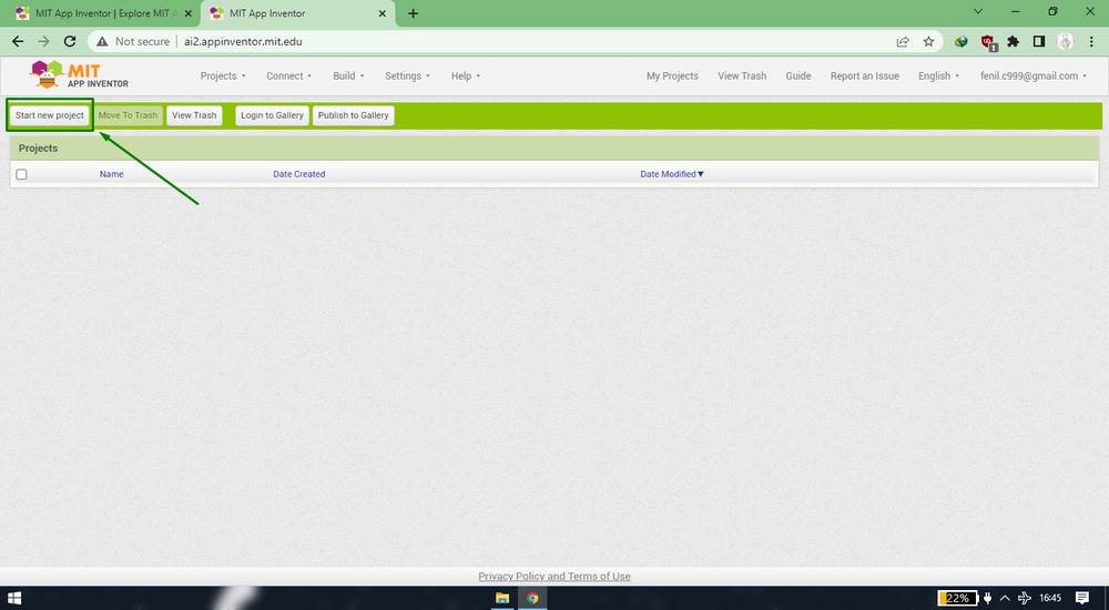
You'll be re-directed to a new page where you have to sign in via google account. AFter signing in, you'll see this page where you need to click
on "start new project"
Give your project a name. After that you will see an interface which is divided into 4 sections,
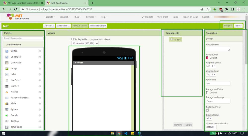
Palette: Where you will find all the components/tools you require to make the app which you just need to drag and drop onto the viewer section,
Viewer: Where you can see how your app will look in you device,
Components: where you'll find all the components that are being used in your app,
Properties: where you can change the properties of the app/components like change color, text, size etc.
These are the sections under "Designer" section which is the frontend of the application. Then there is "block" section which is the backend of
the application where you need to add blocks/cells to configure all the components you added in the "designer" section.
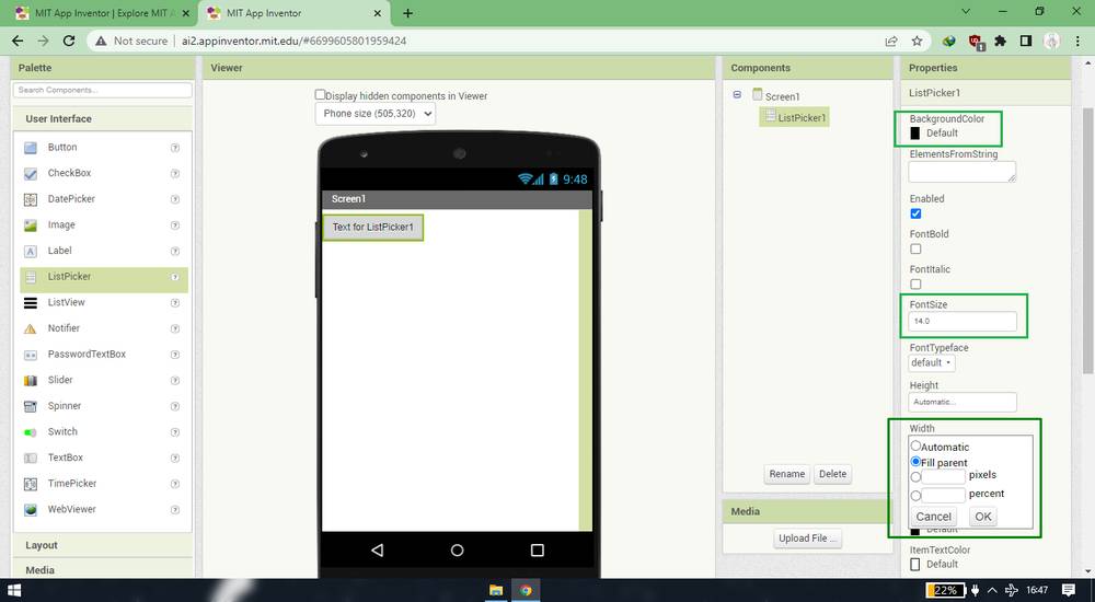
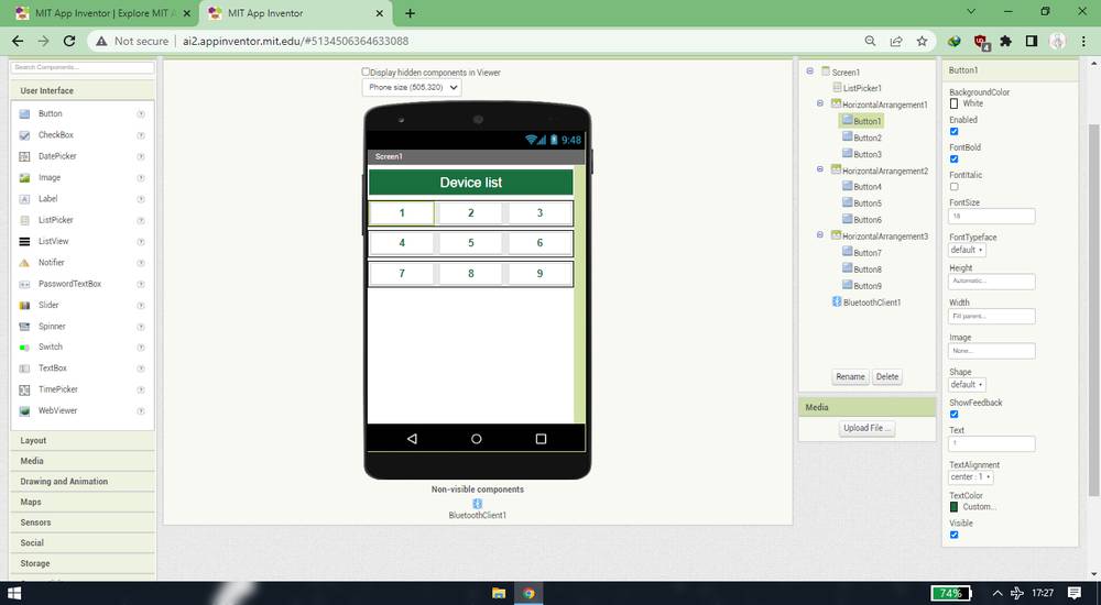
I first wanted to add a menu where i can find the list of all the bluetooth device nearby so i add a component called "ListPicker" under "user
interface"and changed the tab size, text size and color from the properties section,
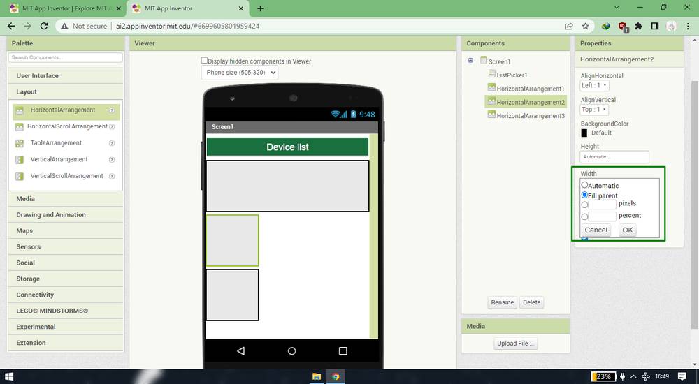
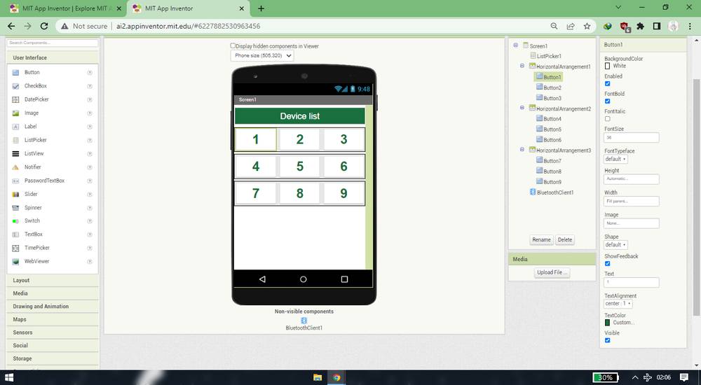
I then wanted to add 9 buttons with number 1-9 which will send the data in form of numbers to the attiny board(more on this later) but i cannot
add the buttons directly. So i added "HorizantalArrangement" under "Layout" and changed the width,
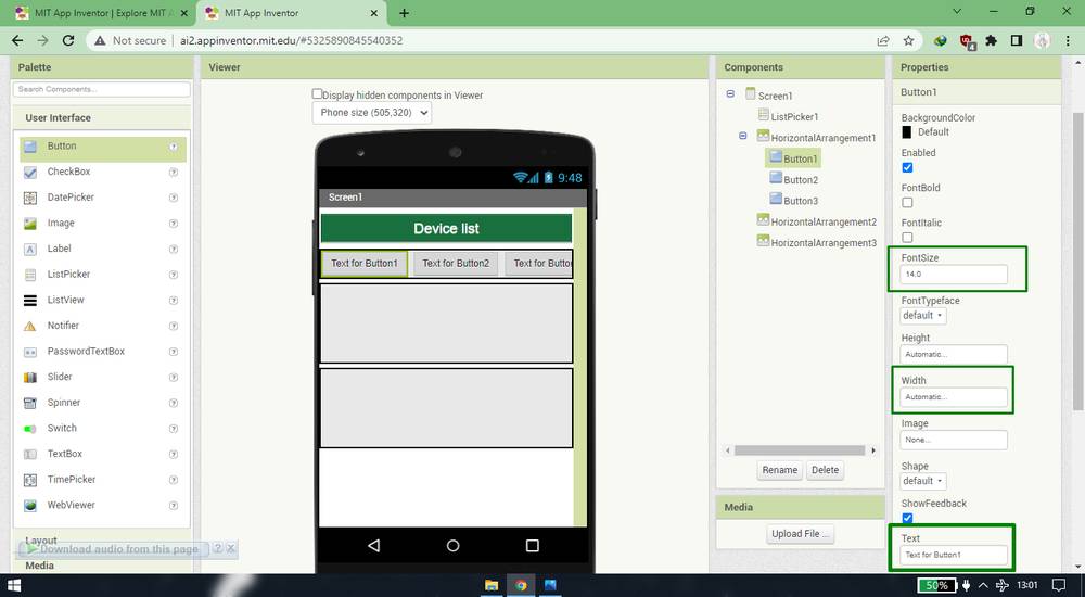
Then i added 3 buttons into each into each horizantal arrangement and changed it's color, size and text,
Lastly i added "BlurtoothClient" under "Connectivity",
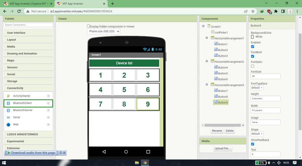
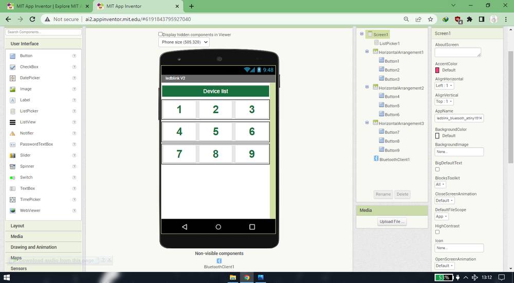
This was how my design of app was looking at the end,
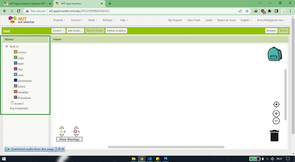
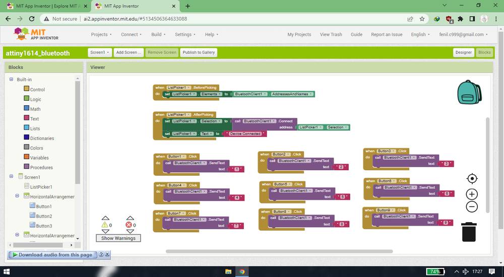
To make the listpicker and every butotn work i went to the block section and added all the blocks/cells necessary. The block section is divideed
into two section,
Blocks: where you will pick up all the necessary blocks,
Viewer: where you'll connect all the blocks(you just need to drag and drop the blocks in order to connect them).
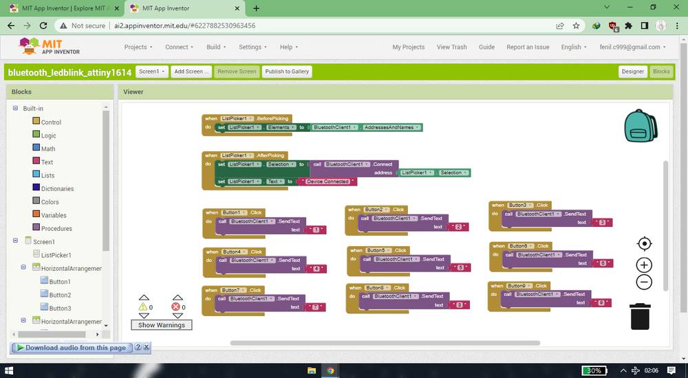
this is how my block section looked after adding and connecting all the blocks,
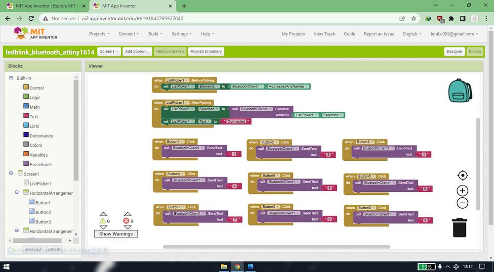
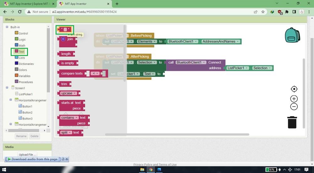
I first worked on the listpicker,
Added BeforePicking and AfterPicking block from the ListPicker,
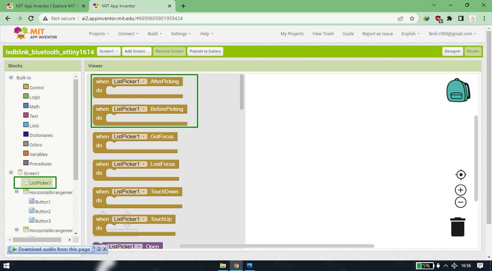
Added Elements block from the ListPicker and connect it with BeforePicking block ,
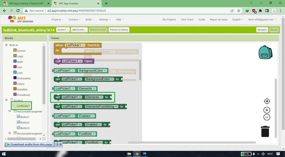
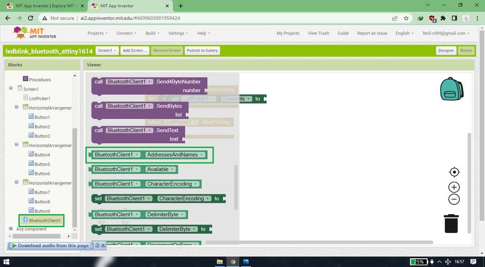
Added AddressesAndNames block from BluetoothClient and connect it with Elements block ,
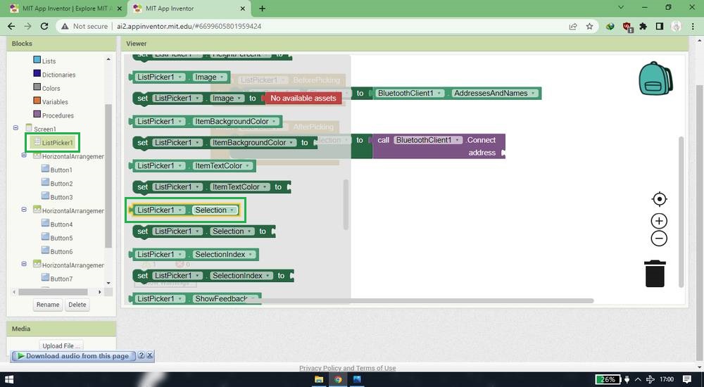
Added Selection block and connect it with AfterPicking block,
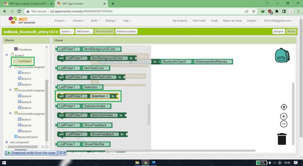
Added .Connect block from BluetoothClient and connect it with Selection block,
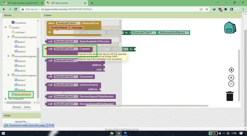
Added Selection block from ListPicker and connect it with .Connect block,
Added Text block from ListPicker and connect it with AfterPicking block,
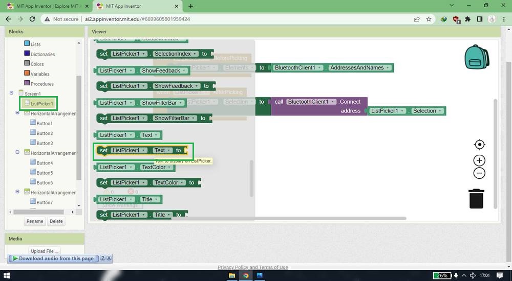
Added text string from the Text and wrote "Connected" inside the text string and connect it with Text block,
I then worked on the buttons,
Added .Click block from the Button1,
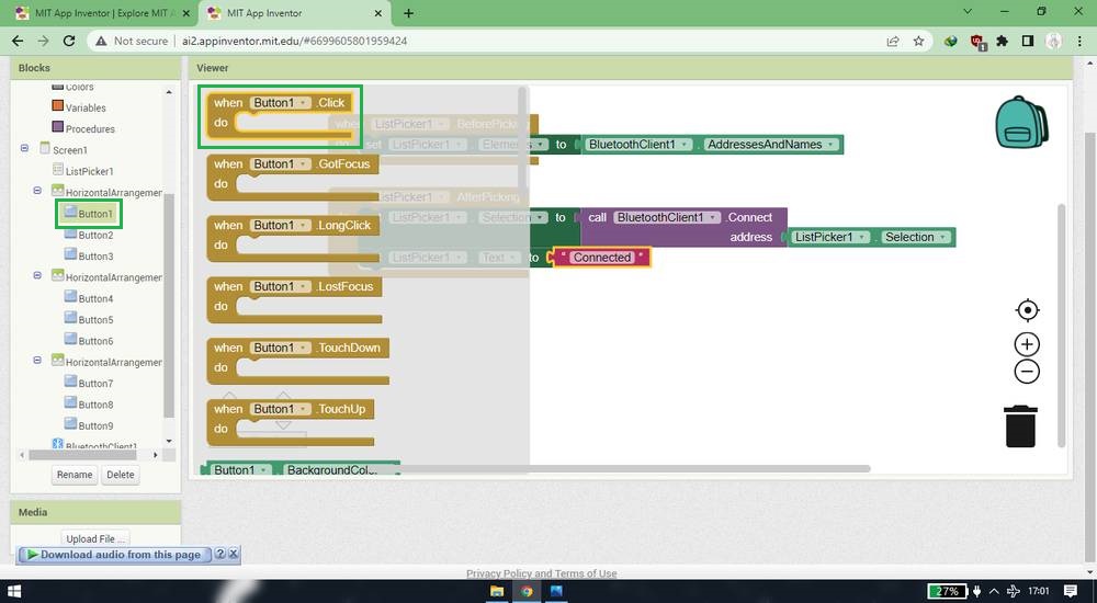
Added .SendText from BluetoothClient and connect it with .Click block,
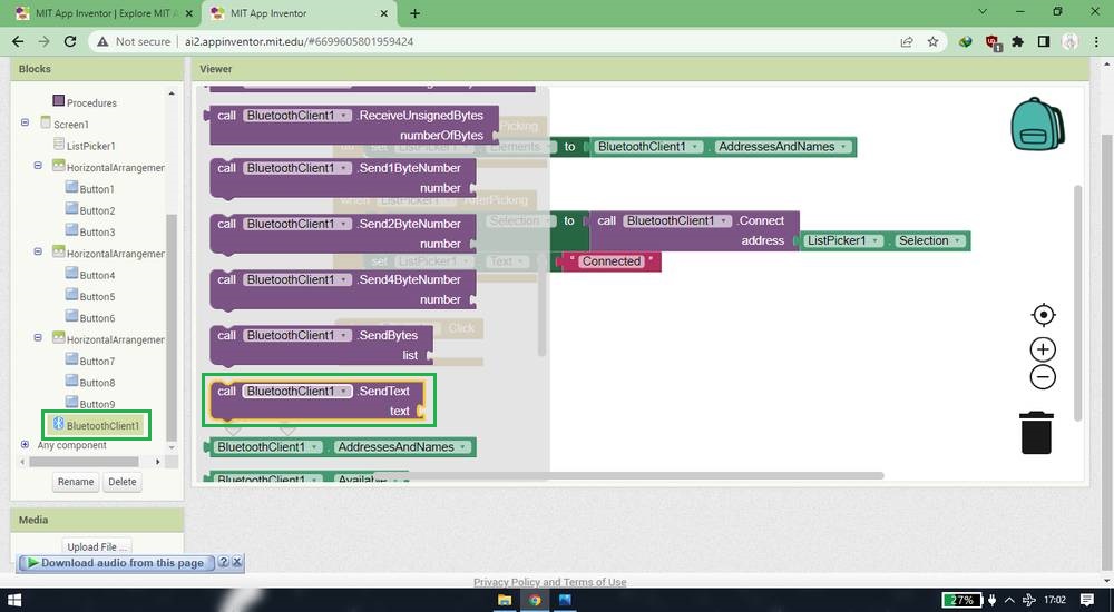
Added text string from the Text and wrote "1" inside the text string and connect it with .SendText block,
I then did the same with all 9 buttons by asigning number 2 to button 2, asigning number 3 to button 3 and so on.
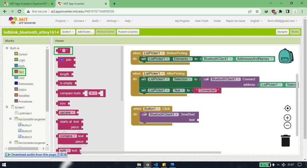
Finally my blocks were ready,
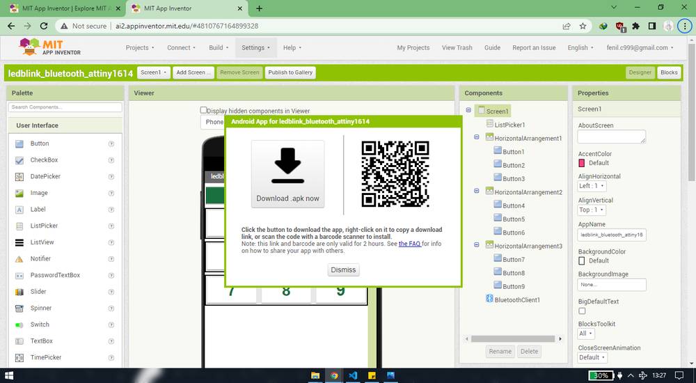
After the components are added in the designer section and blocks are connected in the blocks section, your app is ready to use. After that you can
download the app by clicking on "Android App(.apk)" under build button. You will get option to either download the .apk file into your system(you'll
then need to transfer the file from your system to your phone)
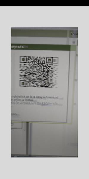
or you can scan the QR code from your android phone and then you can directly download the app into your phone.
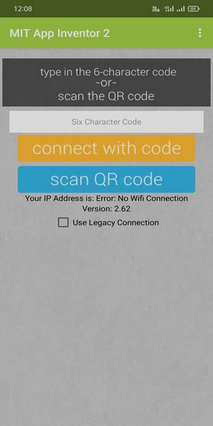
There is another option called "AI companion" under Connect where you need to scan the QR code and you can access the your app into your phone
without downloading the apk. This option is very handy if you are making a lot of changes and need to see the outcome of the changes in your app
without installing and uninstalling it again and again.
You need to download the app called "MIT AI2 Companion": https://play.google.com/store/apps/details?id=edu.mit.appinventor.aicompanion3&hl=en_IN&gl=US
where you can scan the QR code to use the AI companion feature or download the apk file,
Wiring
For wiring and programming, i referred Adrian's website: http://fabacademy.org/2020/labs/leon/students/adrian-torres/adrianino.html#hc05
Wiring of the bluetooth module with the attiny board is similar to the wiring of the attiny board with the UPDI. I first need
to upload the code by connecting the UPDI pins(UPDI-GND-VCC) of the programmer with the UPDI pins of the attiny board,
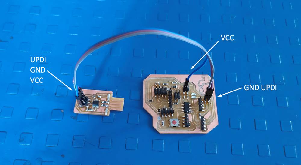
after the code is uploaded disconnect the UPDI programnmer from the attiny board and
connect the GND-VCC-RX-TX pins of the bluetooth module with the GND-VCC-TX-RX pins of the attiny board. You would
then just need to give the power supply to your attiny board after code is uploaded and your bluetooth module is attached. You will get a better
idea refering to this image and video provided by Adrian,
http://fabacademy.org/2020/labs/leon/students/adrian-torres/images/adrianino/a_47.jpg
http://fabacademy.org/2020/labs/leon/students/adrian-torres/images/adrianino/bluetooth.mp4
The reason why i didn't showed the wiring that i used is because instead of powering the atting board externally via battery, i was powering the
atting board via UPDI and i even forgot to disconnenct the UPDI pin from the UPDI programmer and so i don't want to crearte any confusion to the
people refering to my documentation.
Programming
I took the reference of the code that Adrian used: http://fabacademy.org/2020/labs/leon/students/adrian-torres/assignments/adrianino/bluetooth/bluetooth.ino
After modifying the code a bit, this is the code i used for my attiny board,
you can copy the code from here too.
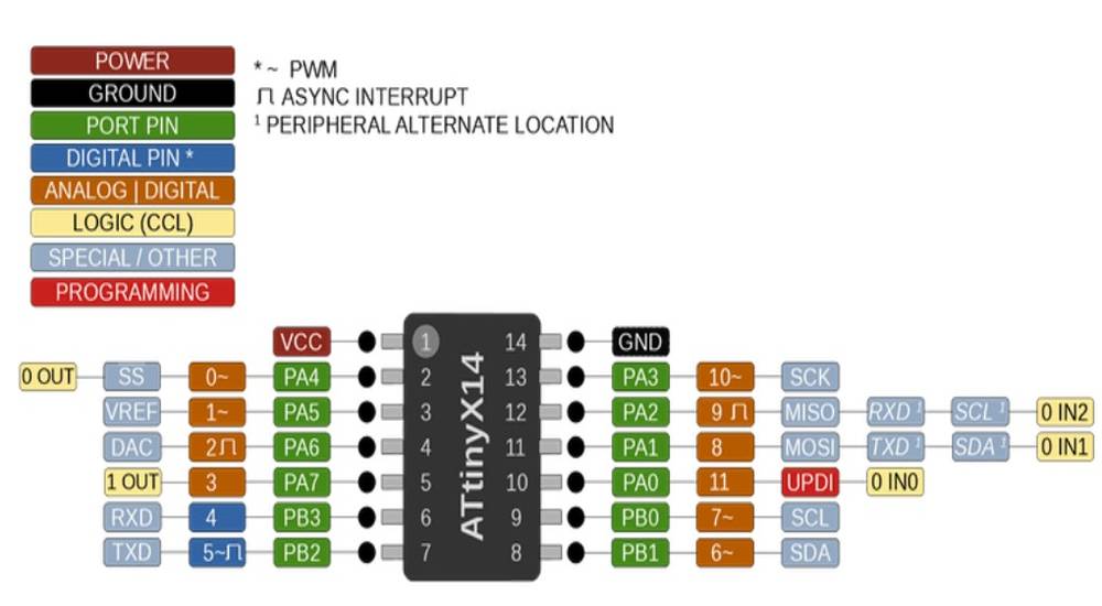
The code is such that when number "1" is sent to the microcontroller, the led will blink once. If number "2" is sent to the microcontroller, the
led will blink twice and so on. Here SoftwareSerial mySerial(1, 0); // RX, TX you define the RX/TX pins of the bluetooth.
if you compare my modified code and the code Adrian used, you'll observe that unlike me Adrian didn't declare the RX/TX pins in his code.
The reason is simple, he assigned the RX/TX pins to PB3/PB2 pins of the attiny 1614 board respectively and since the default pins for RX/TX for
the attiny 1614 board is PB3/PB2 respectively, he didn't need to declare that pins number into his code because the attiny IC will by default show the
data onto the serial monitor on pins PB3 and PB2.
http://fabacademy.org/2020/labs/leon/students/adrian-torres/images/adrianino/a_58.jpg
while i assigned the RX/TX pins to PB4/PB5 pins on the attiny1614 board respectively and one of the PB3/PB2 pins is already consumed by
the button.
and this is the reason why i cannot use codes like this which i use i for Arduino UNO,
Serial.begin(9600);
}
void loop(){
Serial.println("Hello world")
delay(1000);
}
instead i have to use code where i have to use SoftwareSerial library where i can define the RX/TX pins,
It was when my colleague, who is using attiny 1614 ic too, was reading the data into the serial monitor without using the SoftwareSerial
library, when i realised that i made a mistake in designing the board and that i should have defined the RX/TX pins as PB3/PB2 respectively.
Outcome
this is the outcome,
The bluetooth module i was using at the time of testing was HC-02, and it was working fine. However while recording i was using HC-05. I'll
explain the reason why i used HC-02 in the first place later.
Problems with MIT inventor app
So i completed making the app by adding components in the designer section and adding blocks in blocks section and this was how it looked like,
I tested it with my attiny board and it was working fine. However, i thought the size of the button is small so i edited the properties of the button
and this was how the designer and block section looked like,
When i checked the app on my phone through "AI Companion" feature, i was not able to see the list of the bluetooth devices after clicking on the
"Device list" button,
This was the blocks i was using for another app for reading data of ultrasonic sensor(i'll give explaination in more detail later),
As you see the blocks of ListPicker of the led blink and ultrasonc app is same but still i was not getitng the list of bluetooth devices. And yes, i
did tried to download the apk and see if this was a bug, but i still wasn't getting the list.
I then made the whole app again by adding all the components in the designer section and connecting the blocks in the block section again and sure
enough it was working from then on.
Downloadable files of the project from MIT app inventor,
LedBlink
Ultrasonic Sensor
AFter controlling the led onto the attiny 1614 board(output device) through the app, i wanted to read the data of the ultrasonic sensor onto the
app. So again, the procedure is same like blinking the led. Making the app, wiring the bluetooth module and programming.
Making the app
I had no idea how to make app which gives me the reading of the ultrasonic sensor, so i again looked up for the tutorials from where i learned
how to interface the
Arduino UNO through an app with the help of a bluetooth module and then apply the same principle onto my attiny 1614 board. I came across this
tutorial from where i learned how to make an app via MIT app inventor: https://www.youtube.com/watch?v=iAYcOHAgMKM
Making the app for reading the ultrasonic data was similar to making the app for blinking the led. This is how my designer section looked like,
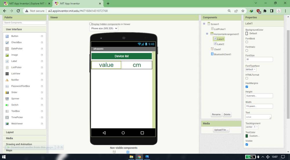
This too has a ListPucker and horizantal arrangement. However instead of using buttons i was using labels(you can use buttons too, i tested that
and it works). I added a fearure called "Clock" under Sensors. So apart from labels and Clock everything is similar to the led blink app.
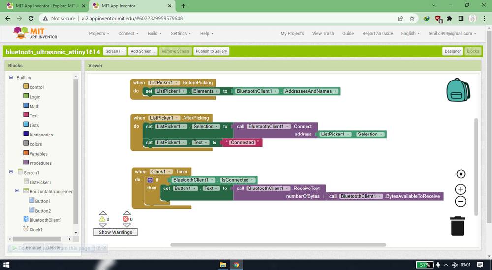
this is how my block section looked like,
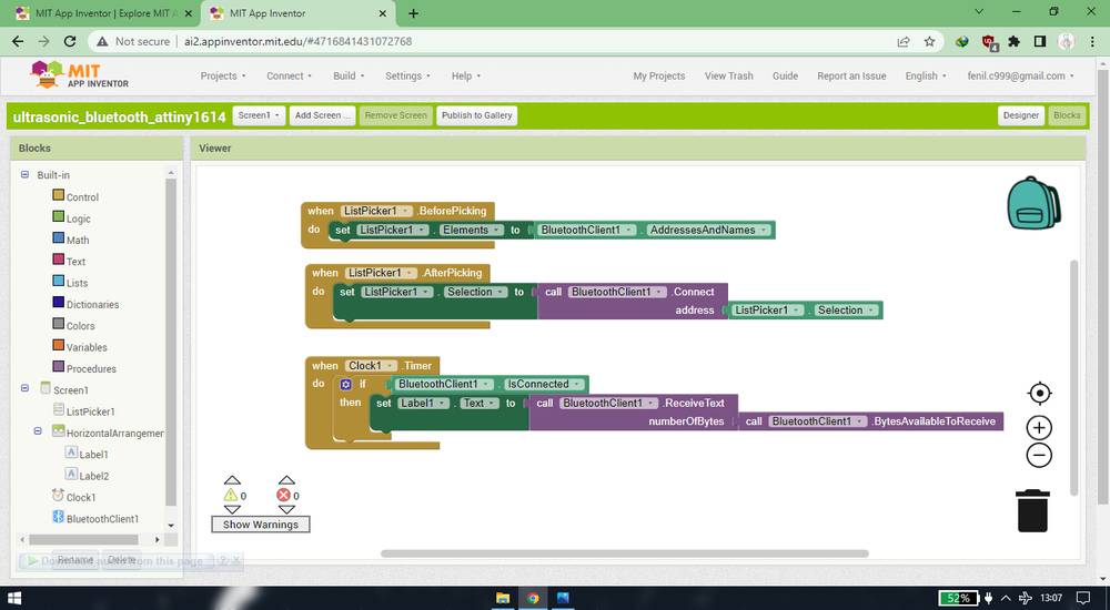
Again, adding and connecting the blocks for the ListPicker was same as the one one for ledblink app. Apart from the blocks for ListPicker, i'll
explain what blocks i added and which blocks i connected below,
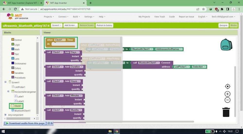
I added .Timer block from Clock,
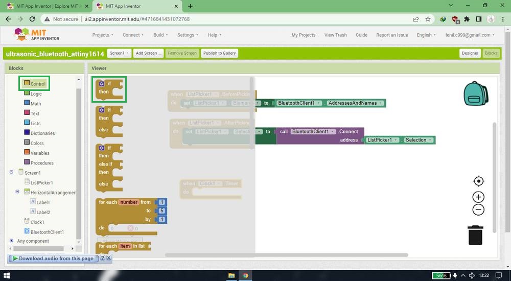
added if/then block from Control and connected it with ,Timer block,
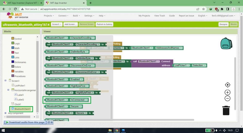
added IsConnected block from BluetoothClient and connected it beside if block,
added Text block from Label and connected it beside then,
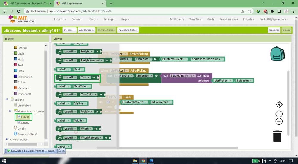
added .ReceiveText block from BluetoothClient and connect it with Text block,
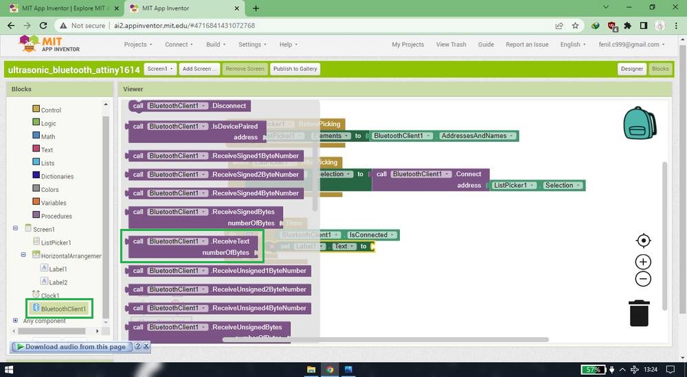
added .BytesAvailableToReceive block from BluetoothClient and connected it with .ReceiveText block,
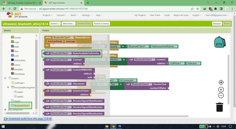
and finally this was how my block section looked at the end,
Wiring
No matter what sensor you want to interface through bluetooth, the connection of the bluetooth with the attiny1614 board(or any other microcontroller
board) will be the same. After the code is uploaded into your attiny1614 board, disconnect the UPDI programmer and then connect
GND-VCC-RX-TX of the bluetooth module with the GND-VCC-TX-RX pins of the attiny1614 board. You'll then need to give the power supply
externally. I however forgot to disconnect the UPDI programmer so i was giving the power supply to the attiny1614 board through the UPDI programmer.
It was much later(june 24, 2022 while writing the assignment for networking and communication) that i realised that while sending the data
to the app via bluetooth, there was no need to
attach the serial UPDI converter either! You just need to connect the HC-05 bluetooth and ultrasonic sensor with the connections mentioned
above and just give power supply to the board externally and you're good to go.
Ultrasonic sensor requires two digital pins for echo and trigger pins so connect GND-VCC-ECHO-TRIGGER pins of the ultrasonic sensor to the
GND-VCC-TwoDigitalPins of the attiny1614 board.
Programming
I took the reference of this code: https://github.com/futureshocked/ArduinoSbS2017/blob/master/_0510_-_Ultrasonic_Distance_Sensor/_0510_-_Ultrasonic_Distance_Sensor.ino
and then modified a bit for my attiny1614board by declaring the RX/TX pins of the bluetooth through software serial liibrary. After a little
modification this was the code i was using(which is the same code i used in the input devices week),
you can copy the code from here too.
Outcome
As mentioned above, i was using HC-02 module for blinking LED. Since the module was working fine for blinking the LED i continued using the HC-02
module for reading the ultrasonic data too not realizing that HC-02 is NOT compatible when it comes to transmitting the data to the app. I spent
countless hours watching tutorials after tutorials, switching from attinyboard to UNO, trying different codes, using readymade apps, modifying
the blocks in the MIT app inventor and not giving attention to the mention of the HC-05 module and only paying attention to the
wiring and code and the design of the app.
Before giving up on the idea of reading the data through bluetooth module, i borrowed my colleague's HC-05 module and sure enough, it worked.
If only i had patience to pay attention to all the details in the tutorials, i would have saved lot of my time. I learned it the hard way, but
if anyone is reading this documentations, use HC-05 module!
Here is the outcome,
Downloadable files of the project from MIT app inventor,
Ultrasonic
esp8266-01
My goal was to send some feedback/data to the app/website, either custom build or readymade and i didn't wanted any distance barrier and that
is why i gave the provision for the wifi module as per my local instructor's instruction.
Using this wifi module was a headache. Every tutorial i see had different board selectoin, different wiring and still all of them were getting
the same results, while i was struggling with getting success with even one of the combination.
To see if the wifi module is working or not, we first need to run the AT commands in the serial monitor
and if it responds back, the module is working. To start with, you need to openthe serial monitor and typr AT and hit enter and the IDE should
respond "OK".
Selecting the board
Just like bluetooth module, i was first trying the esp8266-01 module with the Arduino UNO first becasue it is easy to find it's tutorial.
There were tutorials like this where they were selecting esp8266 as their board,
https://www.youtube.com/watch?v=N5MoXarCF_4
https://www.youtube.com/watch?v=ji71cHaGW8w
You can do that by first adding this link into the Additional board manager URl:
https://arduino.esp8266.com/stable/package_esp8266com_index.json
if there is already a link there, you can paste another link by adding a "," between two links.
After installing the library, i selected the board as "Generic esp8266 module" and i was getting this error when i tried to uplaod a blank sketch,
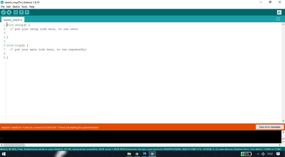
i tried all the combinations like connecting and disconnecting the esp8266-01 module while uploading the sketch, checked the wiring, changing
baud rates but still i was
facing the error everytime.
I then came accross tutorials like this,
https://www.youtube.com/watch?v=KpI9l8xa0MU
https://www.youtube.com/watch?v=6rx-iyUq1Po
where they were selecting Arduino UNO as their board. I again tried all the combinations mentioned above, but still i wasn't getting any response
from the AT commands.
wiring
Just like selecting the board, i came accross a bunch of tutorial and all were having different kind of connection for their esp8266-01 module.
like this tutorial,
https://www.instructables.com/Getting-Started-With-the-ESP8266-ESP-01/
the person is using connections like,
| esp8266-01 | Arduino UNO |
|---|---|
| vcc | 3.3V |
| gnd | gnd |
| rx | tx |
| tx | rx |
| CH_EN | 3.3v |
| gpio0 | nil |
| gpio2 | nil |
| reset | nil |
without using any resistors.
Then i came accross this tutorial where the person was using 1Kohm resistor for the CH-EN pin,
https://hackster.imgix.net/uploads/attachments/987715/ReprogramModuleNano.png?auto=compress%2Cformat&w=680&h=510&fit=max
https://create.arduino.cc/projecthub/ahmedibrrahim/iot-using-esp8266-01-and-arduino-afa35e
Then i came accross this tutorial where the person is using a voltage divider for the RX pins and also using 10Kohm resistor for the VCC and CH_EN
pin.
https://hackster.imgix.net/uploads/attachments/743851/esp-uno-diagram_FhozIF3OCj.png?auto=compress%2Cformat&w=680&h=510&fit=max
https://create.arduino.cc/projecthub/imjeffparedes/add-wifi-to-arduino-uno-663b9e
I tried and tested all the connections mentioned above but i was still getting no response from the seria monitor when i typed the AT commands.
Finally i came accross this tutorial, which was suggested by my one of my instructor- Suvarna Sawant, where the perosn was using a 10Kohm resistor for the CH_EN pin,
https://www.youtube.com/watch?v=01BtAGrSJmc
and when i tested i was finally getting the "ok" response when i typed "AT" in serial monitor. So this is the connectin that worked for the
module i was using,
| esp8266-01 | Arduino UNO |
|---|---|
| vcc | 3.3V |
| gnd | gnd |
| rx | tx |
| tx | rx |
| CH_EN | 3.3v via 10Kohm resistor |
| gpio0 | nil |
| gpio2 | nil |
| reset | nil |
and the board i was selecting was Arduino UNO.
(((ss of at commands ran)))
making app
Once the AT commands ran with the bluetooth attached, i started searching for the tutorial where i can control led through wifi and i came accross
this tutorial: https://www.youtube.com/watch?v=hZAX2d8qrbs
where the person was controlling the led with the blynk cloud website. So this is how i SET UP the website/app for controlling led
through wifi,
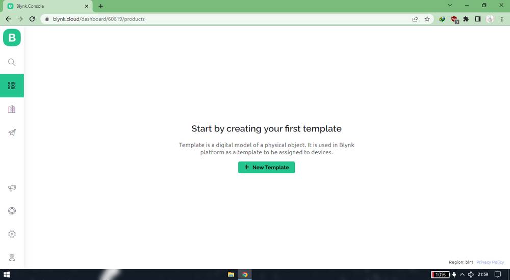
go to the blynk cloud website and create an account: https://blynk.cloud/dashboard/login
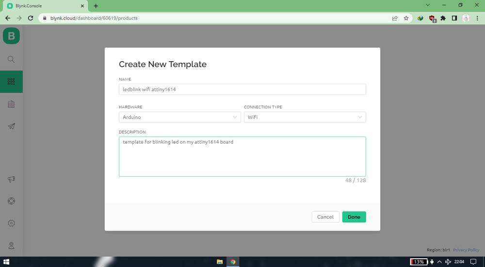
after signing in, click on "New template" buton,
select Arduino as hardware andwifi as connection and fill the other necessary details,
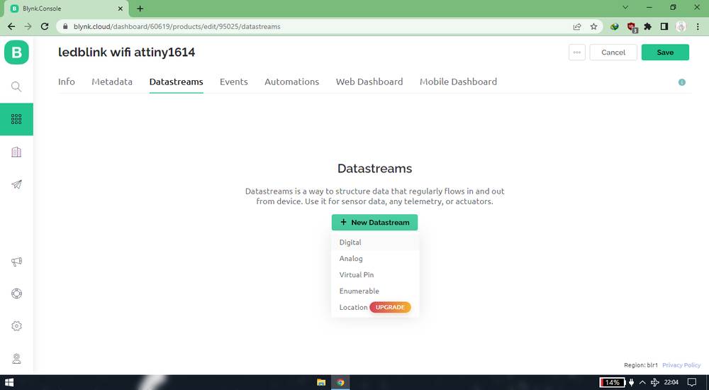
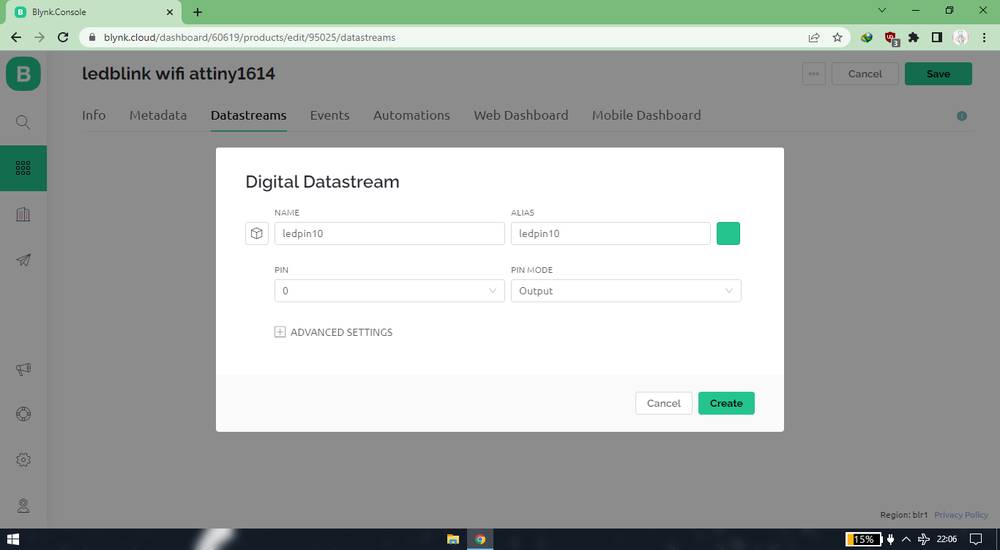
after that go to "Datastreams" tab and click on "new datastream" and then click on Digital,
after that assign the pin number onwhichyou are going to connect the led and set pin mode as "output",
After that go to "webdashboard" tab and drag anddrop the "switch",
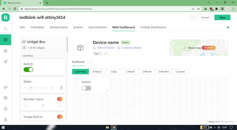
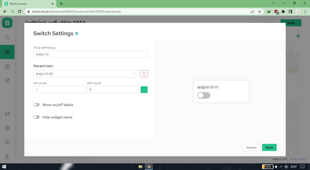
Hover over the switch and click on settings icon and you'll be asked to either choose data stream or create datastream. Since i had
already created the datastream, i clicked on choose data stream and seleted the data stream i created,
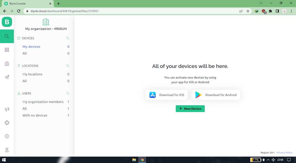
then go to the "search" section and click on new device > Fromn template > select the template you just created,
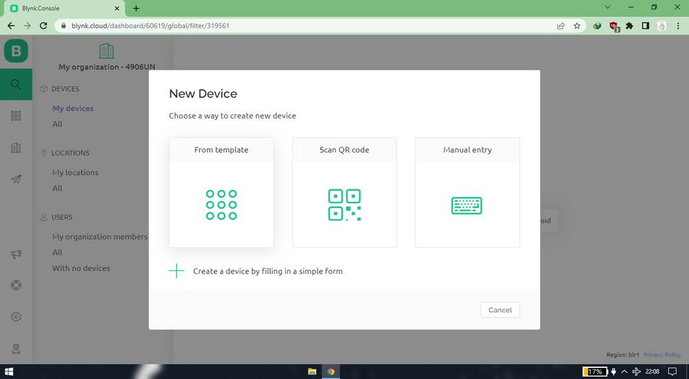
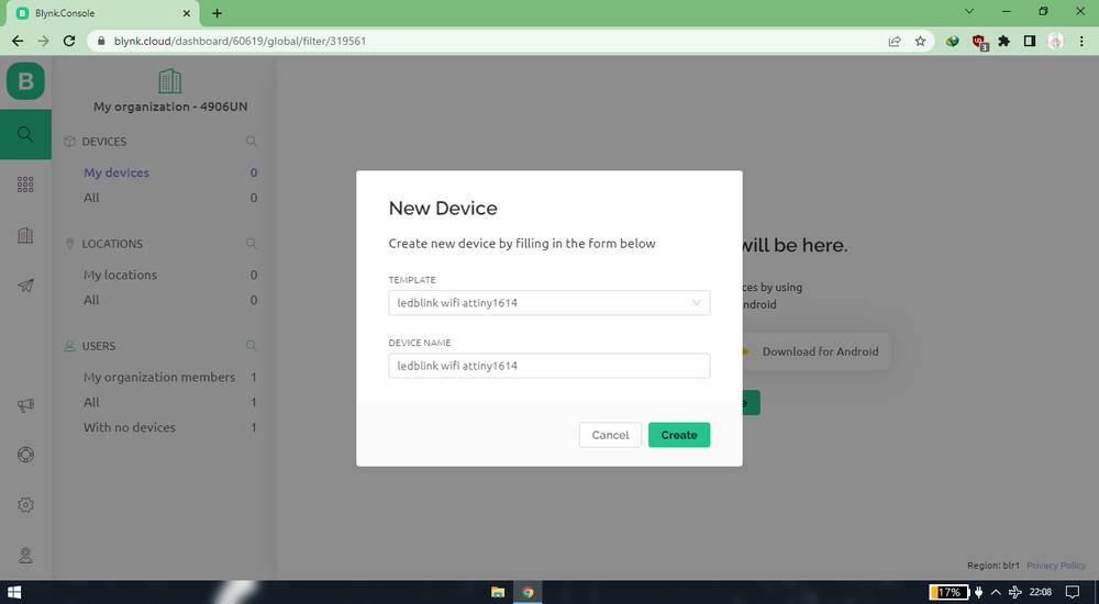
You'll be provided TemplateID, Device name and Authentication token. Copy that because you'll need to paste it in the code.
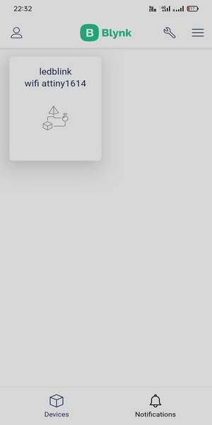
Now youe need to setup the app in your mobile. Download the blynk IoT app: https://play.google.com/store/apps/details?id=cloud.blynk&hl=en_IN&gl=US
Open the app and sign in with the same account in which you made the template. After logging in you'll see the template in your home screen.
click on that template,
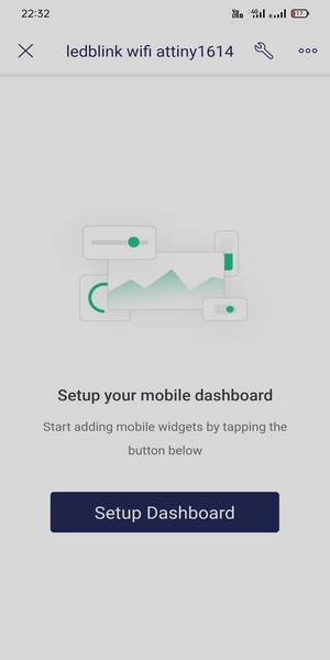
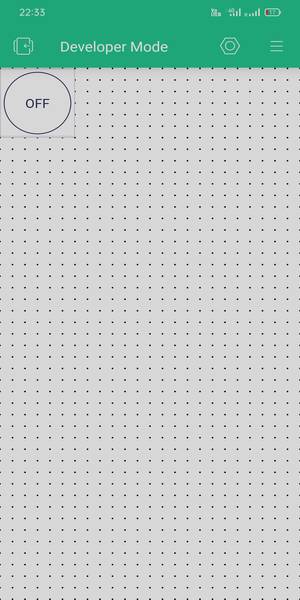
then click on "Setup Dashboard",
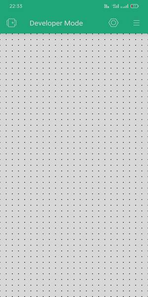
click on the three line icon on the top right corner and tap on button and the button will be put on the canvas,
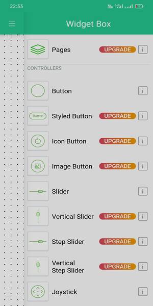
click on the button that is added and select the data stream that you created in the web browser. Give it a title, assign them the value and mode
as you wish,
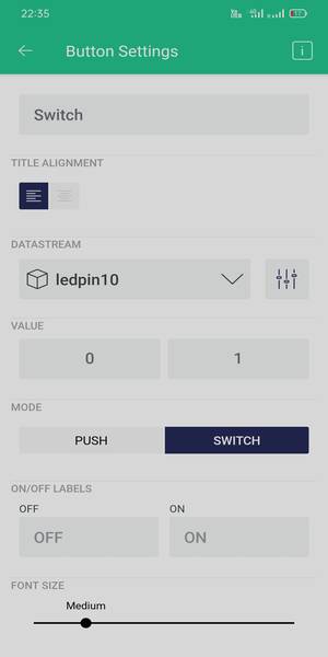
And your app is ready to use. Now the button you added in the web browser and in the app are in sync now. If you turn on the buttonm in the app,
the button on the web browser will also turn on and vice-a-versa.
Programming
Go to this webvsite: https://examples.blynk.cc/
For the board, select "Arduino UNO". For the connection, select "esp8266 wifi shield". For the Example select "Blynk blink" .
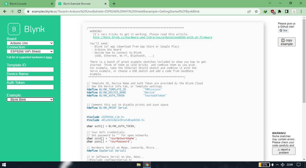
Copth the code and pasrte it in your Arduino IDE. After pasting the code, these are the changes i made in my sketch,
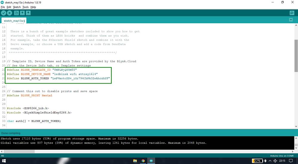
Paste the template id, device name and authentication token here, which you had copied earlier,
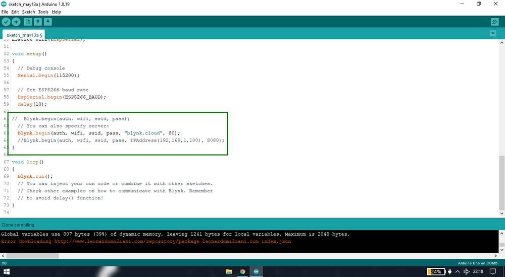
Comment the line Blynk.begin(auth, wifi, ssid, pass); and uncomment the line Blynk.begin(auth, wifi, ssid, pass, "blynk.cloud", 80);
define the RX/TX pins of your wifi module here, SoftwareSerial EspSerial(8, 9); // RX, TX
set the esp8266 buad rate to 15200, as i was unable to initiate the connection with 38400 baud rate,
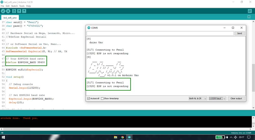
You can change the baudrate of the esp8266 by the using AT+UART commands, but i was getting "Error" message when i tried to run this particular
command.
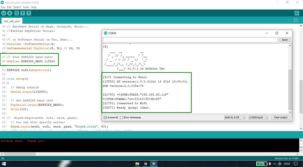
Once the changes are made, upload the sketch with Arduini UNO board selected and after the code is uploaded open the serial monitor and it will
initiate the connection between your wifi module and UNO. You should see line like "Connected to wifi" and "Ready (ping: 12ms)"
This is the sletch i used, you can just change the RX,TX pins that are defined in the sketch,
you can copy the code from here too.
Outcome
After the connection is made between your wifi module and UNO, connect a led to the digital pin which you had defined while making the
template. And turn on/off the led from your web browser or app,
Problems with esp8266-01 module
1 As you saw in the video, the led did turn on and off once without any lag, but after that, though the app and web browser were in sync,
the led was not turning on wheven when i was switching the button on and off. I thought there was some issue with the connwction of the module
and jumper wire so after i adjusted a bit, it was again working properly. It was just a coincidence though, becase off the recording, the led
was again not very responsive ot the button in the app/browser.
2 the module i was using was on of my colleague's. When i got my own module, which i had ordered earlier, i was not able to run the
AT commands. When i searched online, i discovered that the esp8266-01 module needs to be flahsed with the AT firmware. I followed a lot
of tutorials and flahsed a lot of firmwares from different sources but i still wasn't getting any "ok" response when i entered the "AT" in
the serial monitor.
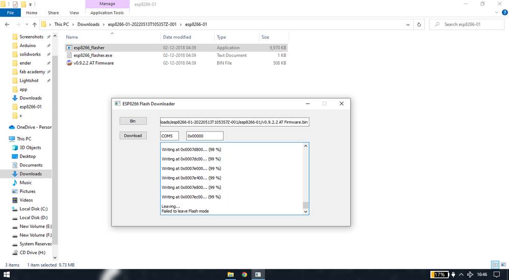
I am sharing one of the tutorials here, you'll find other tutorials onlline if this one doesn't work for you,
https://www.youtube.com/watch?v=Ag_Yk_0AFxs
For the wiring, use the connection mentioned in the video tutorial.
esp8266-12e
Since controllig the led with esp8266-01 was not as responsive as it was with the bluetooth, and also i was not able to run the AT commands with
the new esp8266-01 i ordered, i found the module very unreliable. I then decided to switch the module from esp8266-01 to esp8266-12e.
Since the esp8266-12e module is such where i cannot even insert a jumper wire, i decided to design a board where i will add 22 header pins(8 on the
left 8 on the right 6 at the bottom) and a footprint of the esp8266-12e. However, my instructor Rohan Rege suggested that instead of just
giving header pins, make a breakout board. I was again in the search for some documentation where someone has made a breakout board for esp8266-12e.
I did came accross this one where the person has made a breakout board, but they didn't provide the design file,
http://fabacademy.org/2020/labs/oulu/students/xinhui-hu/Week14_Interface_and_Application.html .
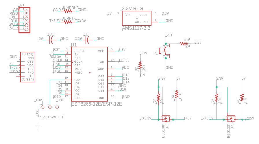
So i had to design the board from the scratch. Rohan Rege did help me make the complete schematic of the board. We took the reference of the
esp-32 WROOM board from the fab academy website,
http://academy.cba.mit.edu/classes/networking_communications/ESP32/hello.ESP32-WROOM.png
apart from the connection and components mentioned in the schematic mentioned above, Rohan suggested to use BSS138 N-Chanel Logic Level Mosfet
for the RX and TX pins
because the the operating voltage of the the attiny1614 board as well as UNO is 5V where the operating voltage of the esp8266-12e/01 is 3V. From
what i understood the signal transmitting from the TX pins of the esp8266-12e won't be understood by the RX pin of the attiny1614 board and
the signal transmitting from the TX pins of the attiny1614 board won't be understood by the RX pin of the esp8266-12e board.
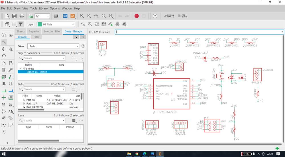
So thia was my final schematic and board for the esp8266-12e,
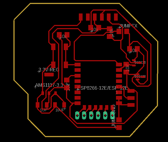
I did a big mistake in making the board. I considered the esp89266-12e as one such IC and kept it in the middle, not realizing that the antena of
the esp8266-12e should be outside of the board. Another thing i could have done was take out all the unassigned pins and connect them to
the header pins(just like rohan suggested me) but i was in a rush so i just took out 6 unassigned pins.
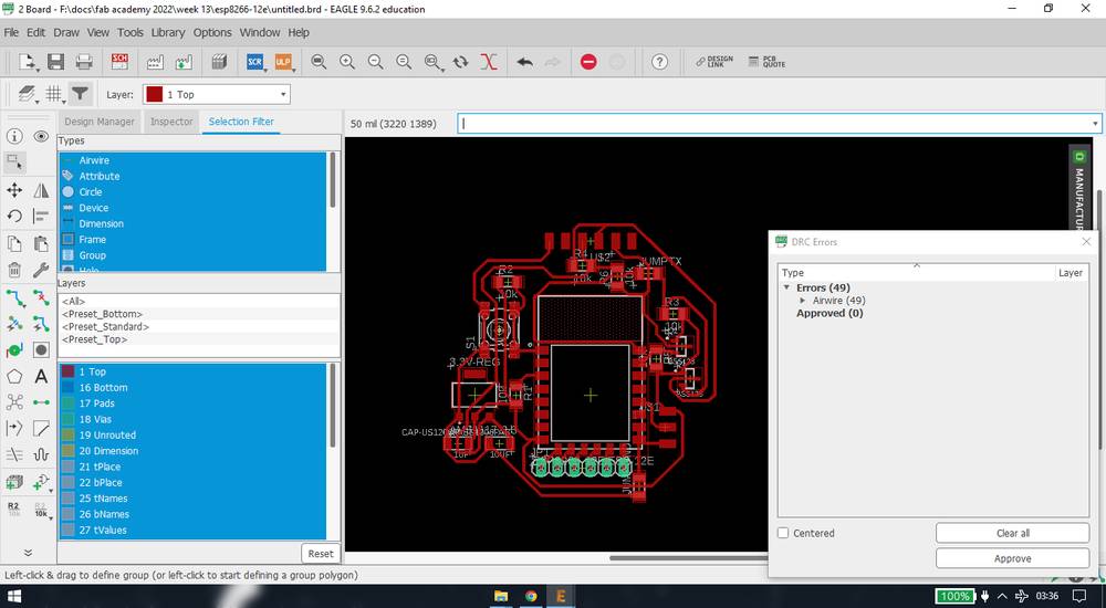
This was some weird error in the design rule check, I however ignored the error and proceeded with miling and stuffing.
I then added the logo of my final project onto the board from inkscape,

These were the components required to make the esp8266-12e board,
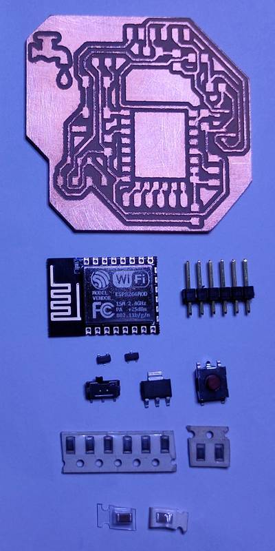
1x esp8266-12e chip
1x 1x6 male header pin(i decided to solder the 6 unassigned pins when i require them and oly solderd the serial pins)
2x BSS138 N-Chanel Logic Level Mosfet
1x SMD slider switch
1x AMS1117 3.3V regulator
1x push button
6x 10Kohm resistor
2x 0ohms resistor
1x 1UF capacitor
1x 10UF capacitor
after the soldering was done, this was how my esp8266-12e board looked
like,
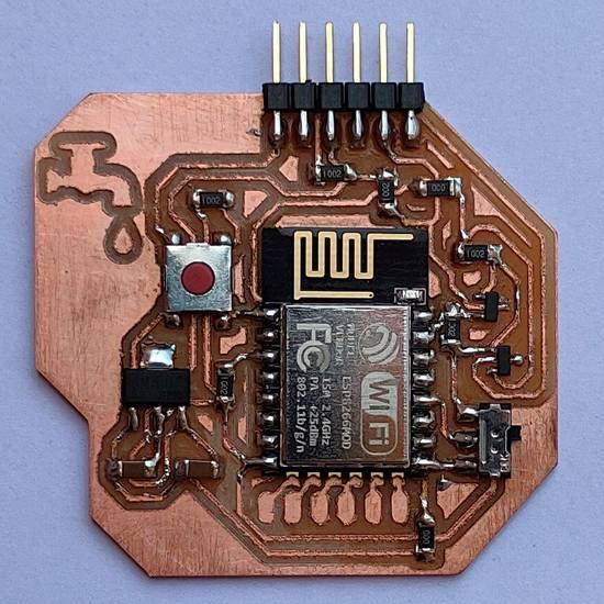
Wiring of the esp8266-12e was simple. Since i have used a 3.3V regulator in the breakout board, i had to connect,
GND pin of the esp8266-12e board with GND pin of UNO,
VCC pin of the esp8266-12e board with 5V pin of UNO,
RX pin of the esp8266-12e board with digital pin pin 9(defined TX in the sketch) of UNO,
TX pin of the esp8266-12e board with digital pin pin 8(defined RX in the sketch) of UNO
I used the same sketch (the one i used for esp8266-01) for the esp8266-12e,
you can copy the code from here too.
I attached a led to the digital pin 10 since the app i made for the esp8266-01 had digital pin 10 assigned for the led.
After the sketch was uploaded and wiring was set, this was the outcome with the esp8266-12e,
There were two things in the esp8266-12e board that different from the esp8266-01 module i was using,
| esp8266-01 | esp8266-12e |
|---|---|
| use of jumper wire and breadboard | every component soldered |
| no use of logic level mosfet | used logic level mosfet for the RX and TX pins |
with these changes applied into the esp8266-12e board, i had high hopes that at least the the communication through the wifi would be very
responsive, unlike the results i was with esp8266-01 module. However, unlike my expectations, there were still some issues with turning the
LED on and off. If you see the video, the LED did turned on and off initially, but in the middle, the LED wasn't responding to the button when i
was switching the button on and off. So i guess i could just have downloaded the PNG files of inner traces and outline of this particular board
from the fab academy website,
http://academy.cba.mit.edu/classes/networking_communications/ESP8266/hello.ESP-01.jpg
instead of designing the whole board because the LED was behaving the same way with esp8266-12e board, as it was behaving with the esp8266-01 module.
esp8266-12e with attiny1614
AFter the esp8266-12e board was working with the UNO, it was time to test it with my attiny board. When i tried to upload the sketch to my
attiny board, i was getting this error while compiling,
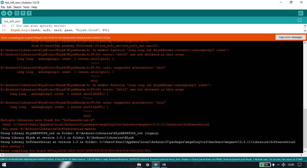
Rohan saw the error and looked up on the internet and told me to change the library verison of blynk to 0.6.0
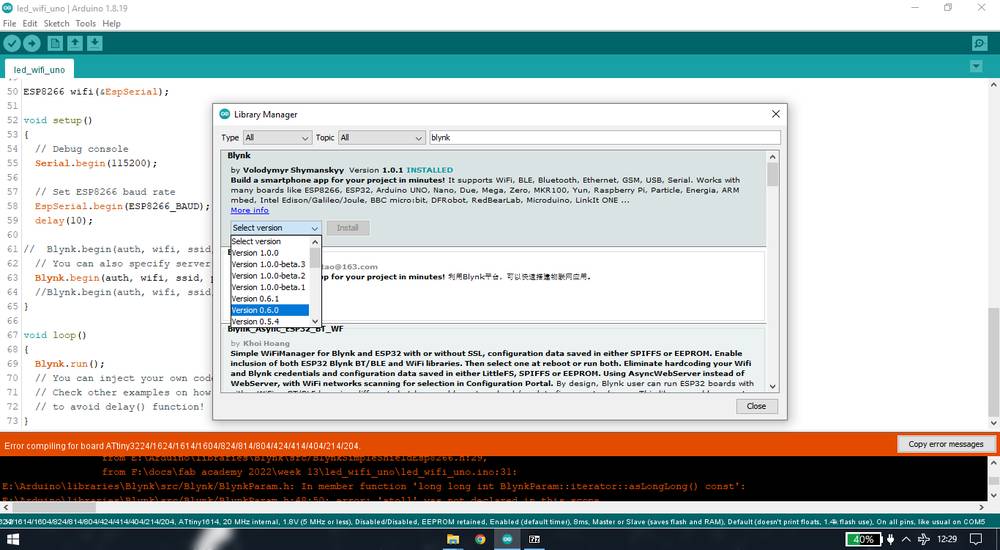
And after updating the library the code was successfully compiled.
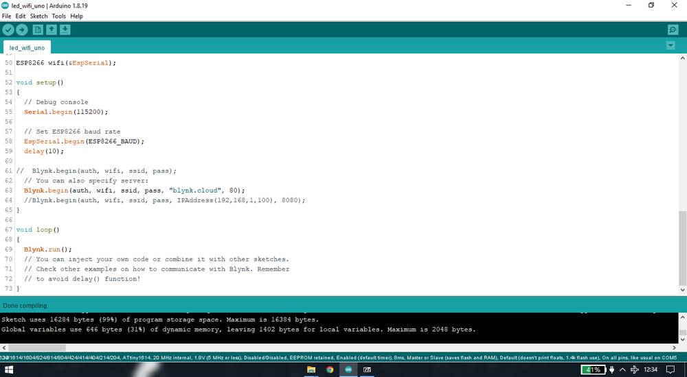
HOWEVER, if you see the message at the bottom, it says "Sketch uses 16284 bytes (99%) of program storage space. Maximum is 16384 bytes."
Since the esp8266-12e alone was consuming 99% of the memory, there was no way i wan squeeze the program for step response, OLED and ultrasonic
in 1%. I know that there could be a different way, just like bluetooth module, to communicate through the esp8266-12e othere than using
blynk cloud, but at this point i didn't want to waste a single second working either with attiny1614 or esp8266. So i decided to change the
IC of my final project board from atting1614 to esp32, since there is an in-build wifi in it and i'll find a lot of documnetation regarding the
esp32 from the previous year students.
Conclusion
Here are all the mistakes i made while making the board with attiny1614 IC,
| What i did | What i should have done |
|---|---|
| For the programming i gave provision for two pins: UPDI-GND | Sould hae given provision for 3 pins: UPDI-GND-VCC |
| soldered two 1Kohm resistor in pyramid structure | Should have gave provision for 2 resistor in series while designing the board |
| For converting 5V to 3V, i used voltage divider with 1K and 2K ohms resistor | Should have used a voltage regulator of 3.3V |
| assigned the RX-TX pins on pins PA4 and PA5(not the default for the IC) | should have assigned RX-TX pins on pins PB3 and PB2(default pins for the IC) |
| assigned the RX-TX pins for wifi module, step response and serial communication(ftdi) to pins PA4 and PA5 | should have assigned different set of pins for RX-TX for every individual module |
| assigned pins for the sensors with this orientation: GND-VCC-SignalPin1-SignalPin2 | should have taken the reference of actual module for the orientation of pins |
Group assignment
For the group assignment, apart from making the app in the MIT app inventor, we tried using other tools like Processing software. Processing
is a tool to show you the data of your input/output device in the form of visual arts which is better than seeing digits when it comes
to interfacing few devices. We also exploerd how to send the data to the firebase and into the the custom app we made. You'll
find more details about processing and firebase in the group asisgnment page here:
https://fabacademy.org/2022/labs/vigyanashram/groupassig/groupassignment11.html
Drip Irritation by Fenil Chandarana is licensed under Attribution-NonCommercial-NoDerivatives 4.0 International![]()
![]()
![]()
![]()